All about civil construction knowledge- PARAM VISIONS

Bar bending schedule (BBS) of a retaining wall. / Calculating the cutting length & weight of reinforcement in a retaining wall.

  Let us make BBS of the retaining wall as shown below.


Given data:

Retaining wall length = 9000mm.= 9m.

Raft width = 2150mm.

Raft depth = 400mm.

Wall height = 2500mm.

Wall width = 300mm

Clear cover = 50mm.


Calculation:

A. Cutting length:

1. Main bar of raft:


Given data:

Reinforcement = T16 @ 150 c/c.

Overlap = 150mm.


Cutting length of raft main bar

= [{2nos.×( a +  b + overlap)} - (5nos. × 90° bend)]

Where, a 

    = [raft width - (2nos. × cover)]

    = [ 2150mm. - (2nos. × 50mm.)]

  a = 2050mm.


b  = [raft depth - (2nos. × cover)]

    = [ 400mm. - (2nos. × 50mm.)]

  b = 300mm.


Cutting length of raft main bar

= [{2nos.×( 2050mm. +  300mm.+ 150mm.)} - (5nos. × 2d)]

= [ {2nos.× 2500mm} - (5nos. × 2 × 16mm)]

= [ 5000mm - 160mm.]

= 4840mm.

= 4.84m.


2. Distribution bar of raft:

Cutting length of distribution bar of the raft

= [ retaining wall length - (2nos. × cover)]

= [ 9000mm. - (2nos. × 50mm.)]

= 8900mm.

= 8.90m.


3. Main bar of RCC wall:

3a. Inner vertical bar:


Given data:

Reinforcement = T16 @ 150 c/c.


Cutting length of the inner vertical bar

= [(300mm.+ a + 150mm.)- (2nos. × 90° bend)]

Where 

a = [(wall height - cover) + (raft depth - cover)]

=  [(2500mm. - 50mm.) + (400mm. - 50mm.)]

= [2450mm. + 350mm.]

a = 2100mm.


Cutting length of the inner vertical bar

= [(300mm.+ 2100mm. + 150mm.) - (2nos. × 2d)]

= [ 2550mm- (2nos. × 2 × 16mm.)]

= [2550mm. - 64mm.]

= 2486 mm.

= 2.486m.


3b. Outer vertical bar:


Given data:

Reinforcement = T12 @ 150 c/c.


Cutting length of the outer vertical bar

= [(300mm.+ a + 150mm.)- (2nos. × 90° bend)]

Where 

a = [(wall height - cover) + (raft depth - cover)]

=  [(2500mm. - 50mm.) + (400mm. - 50mm.)]

= [2450mm. + 350mm.]

a = 2100mm.


Cutting length of the outer vertical bar

= [(300mm.+ 2100mm. + 150mm.) - (2nos. × 2d)]

= [ 2550mm- (2nos. × 2 × 12mm.)]

= [2550mm. - 48mm.]

= 2502 mm.

= 2.5m.


4. Distribution bar of wall:

Cutting length of distribution bar of the wall

= [ retaining wall length - (2nos. × cover)]

= [ 9000mm. - (2nos. × 50mm.)]

= 8900mm.

= 8.90m.


5. Link bar:


Cutting length of the link bar 

= [a + (2nos. × 75mm.) - (2nos. × 90° bend)]

Where 

a = [ wall width - (2nos.× cover)] 

   = [300mm.- (2nos.× 50mm.)] 

a = 200mm.


Cutting length of the link bar 

= [200mm + (2nos. × 75mm.) - (2nos. × 2 × 8mm.)]

= [200mm. + 150mm. - 32mm.]

= 318mm.

= 0.318m.


B. No of bars:

1. Main bars of the raft:

No. of main bars in the raft

 = [{retaining wall length - (2nos. × cover)}÷ c/c distance] + 1

 = [{9000mm. - (2nos. × 50mm.)}÷ 150mm.] + 1

 = [8900mm. ÷ 150mm.] + 1

= 59.33 +1

= 60.33

By rounding off = 61nos.


2. Distribution bars of the raft:

No. of  distribution bars in the raft

 = [{raft width- (2nos. × cover)}÷ c/c distance] + 1

 = [{2150mm. - (2nos. × 50mm.)}÷ 150mm.] + 1

 = [2050mm. ÷ 150mm.] + 1

= 13.66 +1

= 14.66

By rounding off = 15nos.

The distribution bars are provided at the top & bottom sides of the raft.

So, the total no. of distribution bars in the raft

= [2sides × 15nos.]

= 30 nos.


3a. Inner vertical bar

No. of inner vertical bars in the wall

 = [{retaining wall length - (2nos. × cover)}÷ c/c distance] + 1

 = [{9000mm. - (2nos. × 50mm.)}÷ 150mm.] + 1

 = [8900mm. ÷ 150mm.] + 1

= 59.33 +1

= 60.33

By rounding off = 61nos.


3b. Outer vertical bar

No. of outer vertical bars is the same as inner vertical bars

= 61 nos.


4. Distribution bars of wall:

No. of  distribution bars in the wall

 = [{wall depth - cover}÷ c/c distance] + 1

 = [{2500mm. - 50mm.}÷ 150mm.] + 1

 = [2450mm. ÷ 150mm.] + 1

= 16.33 +1

= 17.33

By rounding off = 18nos.

The distribution bars are provided at the inner & outer sides of the wall.

So, the total no. of distribution bars in the wall

= [2sides × 18nos.]

= 36 nos.


5. Link bar:


Link bars are provided along the length side & height of the wall as shown in the above drawing.

No. of link bars along the length side

 = [{retaining wall length - (2nos. × cover)}÷ c/c distance] + 1

 = [{9000mm. - (2nos. × 50mm.)}÷ 300mm.] + 1

 = [8900mm. ÷ 300mm.] + 1

= 29.67 +1

= 30.67

By rounding off = 31nos.


No. of link bars along the height side

 = [{wall height - cover}÷ c/c distance] + 1

= [{2500mm. - 50mm.}÷ 300mm.] + 1

 = [2450mm. ÷ 300mm.] + 1

= 8.16 +1

= 9.16

By rounding off = 10nos.


Total no. of link bars required for retaining wall

= [along length side  × along height side]

= [ 31nos.× 10nos.]

= 310nos.

To know, how to calculate the concrete volume, Go through the article 👇

👀.  How to calculate the concrete volume of a retaining wall?


Now, let us prepare a BBS table for the retaining wall.

Sl. No.

Type of Bar

Dia.

in mm.

Nos.

Length

in m.

Total length

in m.

Weight

in Kg/m.

Total

 bar wt.

in kg.

1.

Main bar of raft

16

61

4.84

295.24

1.578

 465.89

2.

Distribution bar

of raft.

10

30

8.90

267

0.617

 164.74

3.

Main bar of wall


3a.

Inner vertical bar.

16

61

2.486

151.65

1.578

 239.30   

3b.

Outer vertical bar.

12

61

2.50

152.50

0.888

 135.42

4.

Distribution bar of wall.

10

36

8.90

320.40

0.617

 197.69

5.

Link bar

8

310

0.318

98.58

0.395

  38.94

6.

       Total weight of bars =

1241.98

7.

         Add 3% wastage =

  37.26    

8.

The grand total wt. of rebar's =

1279.24 


To go through infrastructure-related articlesclick here.

Thank you for going through these calculation steps. Have a good day 😄.


Share:

Bar bending schedule (BBS) of a storm water drain. / Calculating the cutting length & weight of reinforcement in a storm water drain.

 Let us make BBS of the stormwater drain as shown below.


Given data:

RCC pardi depth = 450mm.

RCC pardi width = 150mm.

Drain bed width = 850mm.

Drain bed thickness = 150mm.

Stormdrain length = 8m.

Clear cover = 50mm.


Calculation:

A. Cutting length:

Given data:

Drain pardi vertical reinforcement     = T10 @ 200c/c

Drain pardi horizontal reinforcement = T8 @ 175c/c.

Drain bed reinforcement-1= T10 @ 150c/c.

Drain bed reinforcement-2 = T8 @ 175c/c.


1. Drain pardi vertical reinforcement:

a. Cutting length of outer vertical reinforcement

= [ {a } + {b} + {c } + {d } - (2nos.× 90° bend)]


= [{pardi width -(2nos.× cover)} + {(pardi depth - cover) + (bed thickness -cover- bed reinforcements )}+ {pardi width  -cover} + {175mm.} - ( 2nos. × 2d)]

= [{150mm. -(2nos.× 50mm.)} + {(450mm. - 50mm.) + (150mm. - 50mm.-10mm.-8mm. ) }+ {150mm. -50mm.} + {175mm.} - ( 2nos. × 2 × 10mm. )]

= [{50mm.} + {482mm.} + {100mm.} + {175mm.} - (40mm.)]

= 767mm.

= 0.767m.


b.  Inner vertical reinforcement 

 Cutting length of inner vertical reinforcement

=  [ {a } + {b} + {c } + {d } - {2nos.× 90° bend}]


= [{pardi width -(2nos.× cover)} + {(pardi depth - cover) + (cover + top bed reinforcements )}+ {cover} + {175mm.} - {2nos. × 2d}]

= [{150mm. -(2nos.× 50mm.)} + {(450mm - 50mm.) + (50mm + 10mm. +8mm. )}+ {50mm.} + {175mm.} - {2nos. × 2 × 10mm.}]

= [{50mm.} + {468mm.} + {50mm.} + { 175mm.} - {40mm.}]

= 703mm.

0.703m.


2. Drain pardi horizontal reinforcement:

 Cutting length of horizontal reinforcement

= [ drain length - (2nos. × cover)]

= [ 8000mm. - ( 2nos. × 50mm.)]

= 7900mm.

=7.9m.


3. Drain bed reinforcement -1:

Cutting length of bed reinforcement-1 

= horizontal reinforcement of pardi = 7900mm.= 7.9m.


4. Drain bed reinforcement -2:

Cutting length of bed reinforcement -2

= [{2nos. × a} + {b} - {2nos. × 90° bend}]


= [{ 2nos.×( bed thickness - 2nos. × cover)} + {bed width - 2nos. × cover} -{2nos. × 2d}]

= [{ 2nos.× ( 150mm. - 2nos. × 50mm.)} + {850mm. - 2nos. × 50mm.} -{2nos. × 2 × 8mm.}]

= [ { 100mm.} + {750mm.} - {32mm.}]

= 818mm. = 0.818m.


Note: Cutting length of top & bottom reinforcement -2 is equal.


B. No. of bars:

1. No of drain pardi vertical bar

= [(drain length - 2nos. × cover) ÷ c/c distance] +1

= [8000mm. - 2nos. × 50mm.) ÷ 200mm.] +1

= 39.5 +1

= 40.5

By rounding off = 41nos.


2. No of drain pardi horizontal bar

= [(pardi depth - cover) ÷ c/c distance] +1 

=  [(450mm. - 50mm.) ÷ 175mm.] +1 

= 2.28 +1

= 3.28nos.

By rounding off = 4nos.


3. No of drain bed bar-1

 =  [(bed width - 2nos. × cover) ÷ c/c distance] +1 

 = [(850mm. - 2nos. × 50mm.) ÷ 150] +1 

= 5+1

= 6nos.


4. No of drain bed bar-2

 =  [(drain length - 2nos. × cover) ÷ c/c distance] +1 

 = [(8000mm. - 2nos. × 50mm.) ÷ 175] +1 

= 45.14+1

= 46.14

By rounding off = 47nos.

Total no. of bed bar-2 for top & bottom

= [2sides × 47nos.]

= 94nos.


Now, let us prepare a BBS table for the stormwater drain.

Sl. No.

Type of Bar

Dia.

in mm.

Nos.

Length

in m.

Total length

in m.

Weight

in Kg/m.

Total

 bar wt.

in kg.

1.

Drain pardi vertical bar.


a.

Outer bar.

10

41

0.767

31.447

0.612

  19.24

b.

Inner bar.

10

41

0.703

 28.823

0.612

  17.64

2.

Drain pardi

horizontal bar

8

4

7.90

31.60

0.395

  12.48  

3.

Drain bed

Bar-1

10

6

7.90

47.4

0.612

  29.00

4.

Drain bed

Bar-2

8

94

0.818

76.89

0.395

  30.37

5.

       Total weight of bars =

  108.73

6.

         Add 3% wastage =

      3.26 

7.

The grand total wt. of rebar's =

 112.00


Note:

1. The depth of the stormwater drain varies according to the road level & slope. But to understand the calculation, a constant value is taken. 


To go through infrastructure-related articlesclick here.

Thank you for going through these calculation steps. Have a good day 😄.

Share:

Bar bending schedule (BBS) of a Chajja (sunshade). Type-1 / Calculating the cutting length & weight of reinforcement in a window projection (sunshade).

 Let us make BBS of the Chajja or RCC sunshade as shown below.


Given data:

Length of sunshade = 1500mm.

Width of sunshade = 900mm.

Sunshade thickness (front) = 75mm.

Lintel beam width = 230mm.

Lintel beam depth = 350nmm.

Main bar = 10∅ @ 150c/c.

Distribution bar = 8∅ @ 150 c/c.

Sunshade clear cover =20mm.

Lintel beam cover = 25mm.


Calculation:

A. Cutting length:

1. Cutting length of the main bar

= [{sunshade thickness - (2nos. × cover)} + (sunshade width - cover) + {2nos.×  (lintel width - cover)} + 100mm. + (100mm. - lintel cover) - (3nos. × 90° bend.) ]

=  [{75mm. - (2nos. × 20mm.)} + (900mm. - 20mm.) + {2nos.×  (230mm. - 20mm.)} +100mm.+ ( 100mm.- 25mm.) - (3nos. × 2 × 10mm.) ]

=  [{75mm. - (40mm.)} + (880mm.) + {2nos.×  (210mm.)} +100mm.+ ( 75mm.) - (60mm.) ]

= [ 35mm. + 880mm. + 420mm. + 115mm.]

= 1450mm.

= 1.45m.


2. Cutting length of distribution bar

= [ sunshade length - (2nos.× sunshade cover)] 

= [ 1500mm. - ( 2nos. × 20mm.)]

= 1460mm.

= 1.46m.


B. No. of bars:

1. No. of main bars

= [{sunshade length - (2nos. × cover)} ÷ c/c distance ] +1

= [{1500mm. - (2nos. × 20mm.)} ÷ 150mm. ] +1

= [ {1460mm.}  ÷ 150mm. ] +1

= 9.73 +1

= 10.73

By rounding off = 11 nos.


2.  No. of distribution bars

= [{sunshade width - cover - main bar dia} ÷ c/c distance ] +1

= [{900mm. - 20mm. - 10mm} ÷ 150mm. ] +1

= [ {870mm.}  ÷ 150mm. ] +1

= 5.8 +1

= 6.8

By rounding off = 7 nos.


If you want to know how to prepare BBS of lintel beam, Go through the article👇

💁 ° How to calculate the cutting length & make BBS of the Lintel bar.


Now, let us prepare a BBS table for the Chajja or sunshade.

Sl. No.

Type of Bar

Dia.

in mm.

Nos.

Length

in m.

Total length

in m.

Weight

in Kg/m.

Total

 bar wt.

in kg.

1.

Main bar.

10

11

1.45

15.95

0.612

   9.76

2.

Distribution bar.

8

7

1.46

10.22

0.395

   4.04 

3.

       Total weight of steel bars =

 13.80

4.

         Add 3% wastage =

   0.414 

5.

The grand total wt. of rebar's in sunshade =

14.21


Go through the article 👇

👀. Bar bending schedule (BBS) of a sunshade. (Type-2) 

Thank you for going through these calculation steps. Have a good day 😄.

Share:

How to calculate the volume of the dome slab? / Calculating concrete volume of the semi-spherical slab.

Let us calculate the volume of the dome slab as shown below.


Now, let us observe a section of a dome slab having a semi-spherical shape as shown below.


Given data:

Slab thickness = 0.15m. = 150mm.

Outer diameter of dome slab = D = 6.3m.

Height of dome slab = Inner radius = 3m.

Inner radius of slab = r = 3m.


Calculation:

The volume of the semi-spherical slab is calculated by the formula

= [2/3 × π × { ( R )3( r )3 }]

Where

R = outer radius

      = D/2 = [6.3m ÷ 2] = 3.15m.


The volume of the semi-spherical slab

= [2/3 × 3.142 ×  { ( 3.15m. )3( 3m )3 }]

= [2/3 × 3.142 × { 31.256 - 27}]

= [ 2.094 × 4.256 ]

= 8.912 cum.

= 314.72 cu ft.


The outer surface area of the semi-spherical dome slab

=  [2 × π × ( R )2]

=  [2 × 3.142 × ( 3.15 )2]

= 62.35 sq m.

= 671.16 sq ft.


To go through all types of quantity estimate articles, click here.

Thank you for going through these calculation steps. Have a good day 😄.

Share:

What should be the minimum distance between reinforcement bars?/ Minimum spacing between individual reinforcements.

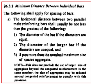
 According to the IS-456:2000, the minimum spacing between the individual reinforcement bars is determined as follows.


A. Minimum horizontal spacing:


As per IS-456:2000, the minimum horizontal distance between the individual bars shall be the maximum of the following three conditions.


1. Equal diameter bars:


As shown in the above drawing, if all the bars spaced horizontally are of equal diameter, i.e. 20mm., the spacing as per condition-1 is 20mm.


2. Unequal diameter bars:


As shown in the above drawing, if all the bars spaced horizontally are of unequal diameter, i.e. 25mm. & 16mm, the spacing as per condition-2 is 25mm.

3. Aggregate size:

 Suppose, we use a coarse aggregate of 20mm. size, the minimum spacing as per condition - 3 is

= [nominal size of coarse aggregate + 5mm.]

= [20mm. + 5mm.] = 25mm.

Here, the maximum value in all three conditions is 25mm.

 So, we have to consider 25mm. as the minimum horizontal spacing.


If we use a coarse aggregate of  25mm. size., the minimum spacing will be

= [25mm.+ 5mm.] = 30mm.


 Here, we have to consider 30mm. (greater value)  as the minimum horizontal spacing.


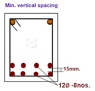
B. Minimum vertical spacing:


As per IS-456:2000, the minimum vertical distance between the individual bars shall be the maximum of the following three conditions.


1. Minimum requirement:


 In any situation ( condition-1), the minimum vertical bar spacing shall not be less than 15mm.

If the diameter of the bars is  ≤12mm., the minimum vertical distance shall be 15mm. In this case, we cannot consider 12mm. ( bar dia.) as the minimum spacing.


2. Aggregate size:

 Suppose we use a coarse aggregate of 20mm. size, the minimum vertical spacing as per condition - 2 is

= [ 2/3 × nominal size of coarse aggregate ]

= [2/3 × 20mm.] = 13.33mm.


3. Bar diameter:


As you can observe in the above drawing, if the diameter of the vertical layer of bars is 20mm., the minimum vertical spacing shall be equal to the bar diameter, i.e. 20mm.

Out of all these three conditions, the maximum value is 20mm.

 Here, we have to consider 20mm. as the minimum vertical spacing.


Note:

1. Whatever might be the permutation & combination of conditions, in all cases you have to choose the greater value as a minimum spacing.

2. Minimum spacing is the clear span ( not c/c distance) between the individual bars. 


👀  To go through all types of construction-related procedures & checklistsclick here.

Thank you for going through this article. Have a good day 😄.
Share:

Translate

Blog Archive

popular posts

Recent Posts

Google search