All about civil construction knowledge- PARAM VISIONS

What are bend deductions for different angles in reinforcement bars?/Bend elongation in reinforcement bars.

Let us go through some of the FAQs related to the bend deductions in rebars.


1.  Why do we make bend deductions in the cutting length calculation of reinforcement bars?

When we bend a steel bar, the length of the bar is increased due to stretching at the outer periphery of the bar. To compensate for this reinforcement bar elongation, we deduct the increased length while calculating the cutting length of the steel bars.


2.  What are the factors that affect the bend elongation in rebars?

1. Degree of bend :
    The length of the steel bar increases with the increase in the degree of bending.

2. Grade of steel:
    The bending length of the rebar decrease for the higher grade of the steel. That means, the higher the grade of steel, the lesser the increment in length of the bar.

3. What are the bend deductions for the different angles of steel bar bending?


1.  45° bend:


For 45° bend, the bar elongation will be 1d and therefore we deduct 1d for 45° bend in the cutting length calculation. 

Where d = diameter of the steel bar.

Suppose the diameter of the rebar is 8mm, having a 45° bend,

 The bend deduction = 1d = [1 × 8mm] = 8mm.


2.  90° bend :


For the 90° bend, the bar elongation will be 2d and therefore we deduct 2d for the 90° bend in the cutting length calculation. 

 If the diameter of the rebar is 8mm, having 90° bend,

 The bend deduction = 2d = [2 × 8mm] = 16mm.


3. 135° bend:


For the 135° bend, the bar elongation will be 3d and therefore we deduct 3d for the 135° bend in the cutting length calculation. 

 If the diameter of the rebar is 8mm, having 135° bend,

 The bend deduction = 3d = [3 × 8mm.] = 24mm


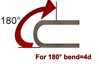
4. 180° bend:


For the 180° bend, the bar elongation will be 4d and therefore we deduct 4d for the 180° bend in the cutting length calculation. 

 If the diameter of the rebar is 8mm, having 180° bend,

 The bend deduction = 4d = [4 × 8mm.] = 32mm


To get the answer to all types of your construction queries,

Click 👀.  Terms & definition.


Thank you for going through these calculation steps. Have a good day 😄.

Share:

How to calculate wall tiles?/ Calculating the number of wall tiles required for a bathroom.

 Let us now calculate the area and number of wall tiles required for the bathroom as shown below.


Given data:

Length of the bathroom = 9 ft.

Width of the bathroom = 7 ft.

Bathroom height = 9 ft.

Door size =2.5ft × 6.5 ft

Window size = 1.5ft × 3ft.

Let us select a tile of size 10" × 16", and let us fix the tile up to the full height of the bathroom.


Calculation:

Now, the number of wall tiles required

= [Area of bathroom wall ÷ area of one tile.]

First, we will calculate the area of the bathroom wall that should be tiled & the area of a single tile.

Bathroom wall area

= [{(2nos.× wall-length )+ (2nos × wall width)} × wall height ]- [( door area ) + ( window area )]

= [ {( 2nos. × 9ft. ) + ( 2nos. × 7ft.) }× 9ft.] - [(2.5ft × 6.5ft.) + ( 1.5ft × 3ft )]

= [ { ( 18ft. + 14ft. } × 9ft.] - [ ( 16.25sqft. + 4.5sqft.]

= [ 32ft. × 9ft.] - [ 20.75 sqft.]

= 288 sqft. - 20.75 sqft.

= 267.25 sqft.


Area of a tile

= [10" × 16"]

= [0.833ft × 1.333ft.]

( Dividing by 12, we have converted inches into ft. )

= 1.111 sqft.

The number of wall tiles required

 = [Area of bathroom wall ÷ area of one tile]

 = [267.25 sqft.÷ 1.111sqft.]

 =240.55 nos.

Taking 10% extra for wastage & future use

= [240.55 nos. + (240.55 × 10) ÷ 100]

= [240.55nos. + 24.55 nos.]

= 265 nos.


To go through all types of quantity estimate articles, click here.

Thank you for going through these calculation steps. Have a good day 😄.

Share:

How to calculate the percentage of steel in the cross sectional area of a column?/Calculating the reinforcement ratio in a column.

 As per IS-456, the cross-sectional area of longitudinal reinforcement in columns shall not be less than 0.8%  and should not exceed 6%.

Now, let us find out the percentage of longitudinal steel in the c/s area of a column as shown below.


Given data:

The breadth of column = b = 450mm.

Depth of column = d = 300mm.

Longitudinal corner bars d1= 20T- 4nos.

Longitudinal mid bars d2= 16T- 4nos.


Reinforcement ratio of the column 

 = Sectional area of steel ÷ Sectional area of column concrete.

 = Ast ÷ b × d.

First, we will calculate the sectional area of all the longitudinal bars

Ast = [{4nos × c/s area of 20mm bars } + { 4nos. × c/s area of 16mm. bars }]

        =[{4nos. × (π × d12) ÷ 4} + {4nos. ×  (π × d22 ) ÷ 4}]

Here, d1 & d2 are the diameters of a particular bar.


Ast = [{4nos. × (3.142 × 202) ÷ 4} + {4nos. ×  (3.142 × 162 ) ÷ 4}]

       = [{4nos. × (1256.8) ÷ 4} + {4nos. ×  (804.35 ) ÷ 4}]

       =[{1256.8} + { 804.35 }]

       = 2061.15 mm2 


Reinforcement ratio

= [Ast ÷( b × d)].

= [2061.15 mm2  ÷ (450mm × 300mm)].

= [2061.15 mm2 ÷135000 mm2]

= 0.01526

Go through the article👇

👀.  Checklist for column reinforcement./ Points to be checked in column reinforcement.

Reinforcement ratio of the column


The percentage of steel in the c/s area of the column

= reinforcement ratio × 100

= 0.01526 × 100

=1.526%

The calculated percentage of steel is between 0.8% & 6%. Hence safe.

Note: The sectional area of lateral ties ( stirrups) is not considered while calculating the percentage of steel in a column section.

For you 👇

Why don't we deduct the steel volume while calculating the concrete volume in  RCC structures? 

Share:

What is 3D foam wall panel stickers?/ What is self adhesive 3D wall stickers?

 Let us now go through some of the quarries related to the 3D foam wall stickers.

1. What are 3D foam wall panel stickers?


3D foam wall panel stickers are self-adhesive wall stickers to decorate the interiors of buildings. They are made of polyethylene protective foams manufactured in a different colored tile design with 3D surface finishings. The back surface is coated with gum or glue for the sticking purpose.  


2. Can we stick 3D foam wall panel stickers on all types of wall surfaces?

3D foam wall stickers need a smooth surface finish to make a good adhesion and ensure long-lasting sticking abilities. 

They can be used over 

👉 1. Painted wall surfaces.

     2. Surfaces having wallpapers.

     3. Plastered surface finished with wall putty. 

     4. All types of wooden surfaces and cabins.

     5. Glass & painted metallic surfaces.


They cannot be used over

👉 1. Rough brick wall surfaces without plaster.

      2. Wall having dampness due to seepage or any such factors. 


3.  What is the size & thickness of 3d wall panel stickers?

The thickness of the 3D foam stickers varies from 5mm - 8mm. 

The standard size of the foam wall sticker is 70cm × 77cm.

They are available in other sizes as per manufacturers' design in 70cm × 70cm., 65cm ×  77cm. etc.


4. What are the advantages & disadvantages of 3D foam wall stickers?

Advantages:

1. The sticker surface can be washed easily and all types of stains can be removed. 

2. Provides an aesthetic look to the wall surface with a 3D surface finish.

3. The spongy surface provides protection from any casualties to children and elderly people when compared to the hard wall surface.

4. You can do the sticking job by yourself and no skilled worker is needed to fix the foam stickers.

5. They are lightweight, & you can order them easily from online stores as per your choice.


Disadvantages:

1. They are flammable and are not fireproof.

2. Touching with any sharp objects (knife ) may cut them or make a scratch mark over them.

3. If you want to paint the wall, removing them is a time-consuming job & you have to scratch the wall surface to remove the glue before painting.


5. What is the price of 3D foam wall panel stickers?

The price of the 3D foam wall sticker depends upon

1. The thickness of the foam sticker.

2. The length & width of the sticker.

3. Type of sticker design, color & pattern. 

4. Manufacturer & brand of the3D sticker.

Considering the above factors, the price of the 3D wall sticker ranges from INR 40/- to INR 100/- per square foot.


6. Can we paint the surface of  3D foam wall stickers?


No. you cannot paint the 3D foam stickers surface, as it is made of polyethylene material. If you want to change the color, you have to purchase a new one as per your color choice.


7. Can we use the 3D foam wall stickers over the exterior wall surface?

It is always advisable to use the 3D foam stickers over the interior wall surface as they are made of delicate material. Due to the external atmospheric conditions, they will fade easily & will not last for a longer period of time.


8. Can we use 3D foam stickers over room ceilings?


Yes. 3D foam stickers give a royal look when you use them to decorate the ceilings.

 To get the answer to all types of your construction queries,

Click 👀.  Terms & definition.

Thank you for going through this article. Have a good day 😄.

Share:

What is chair bar in construction work?/ Spacing & purpose of providing chair bars in construction.

 Now, let us go through some of the FAQs related to the chair bar used in the construction work.


1.  What is a chair bar in construction?


A chair bar is a support bar placed and tied in between the upper & lower reinforcement cage to maintain the gap and stability of reinforcement. As they are somewhat bent up like a chair, and provides a sitting arrangement for the upper cage, we call it, a chair bar in civil engineering.


2.  What is the purpose of providing a chair bar in construction reinforcement?


1. To maintain the required gap between the upper & lower reinforcement cage in footings, slabs, raft foundations, etc.

2. To maintain the clear cover for the reinforcement at the time of concrete vibration.

3. Protecting the top & bottom cage from displacement and sagging at the time of concreting work, due to the movement of trolleys, walking of the workers, dead load of the fresh concrete, etc.

4. Providing extra support for the reinforcement bars.


3. What should be the diameter of chair bars used in construction?

Generally, the chair bars are made of rebars of diameter 12mm and above. The most common dia. bars are 12mm, 16mm, and in some cases 20mm. 

In rare cases, it is OK to use 10mm bars in slabs, when there is no extra external load other than reinforcement cage load. 

The reason for not using the smaller dia. bars ( < 12mm ) is, they tend to bend or buckle for the overladen loads due to which, the main purpose of providing the chair bar becomes useless.


4. What should be the spacing of chair bars in construction?

The spacing of the chair bars depends on several factors like,

1. Diameter of the bar used in making a chair. 👉 The larger the diameter of the bar, the more the spacing is, and vice versa.

2. Type of the structural member.

3. Diameter of the reinforcement bar of the RCC structure.

4. External loads that act over the chair bar other than rebar cage.


As such, there no specification for the spacing of chair bars in the construction.

In general, 1no. of chair bar is provided for the reinforcement cage area of 0.8sqm - 2sqm., depending upon the above factors.


5. What is the number of chair bars required in 10sqm. of structural reinforcement area?

Let us consider providing 1no. of chair bar per sqm. area of RCC structure.

The no. of chair bars 

  = Area of structural reinforcement in sqm ÷ chair bar per sqm.

  = 10sqm ÷ 1sqm.

  = 10nos.


To get the answer to all types of your construction queries,

Click 👀.  Terms & definition.


Share:

How to calculate the cutting length of chair bar in footings?/ Calculating the cutting length of bar chair in civil construction.

The chair bars are placed in the footings to support the top and bottom reinforcement cage as shown below.


You keep it in your mind that, always the top head or supporting part of the chair should be tied to the bottom layer bar( top distribution bar ) of the upper cage & the bottom leg part of the chair should be anchored to the bottom layer bar (bottom main bar ) of the lower cage. 

For your understanding, I have given a drawing of a chair bar showing three parts in it, i.e. head, height & leg.


From the above drawing, we can say that

The cutting length of the chair bar

  = [{(2nos.× height ) + (1no. × head ) + ( 2nos. × leg)} - (4nos. × 90° bend )]

  = [ 2H + E + 2L - 8d ].

 Let us now redraw the above-given footing with dimensions & specifications for the calculation purpose.


Given data:

The diameter of the chair bar = d =12mm.

Top & bottom clear cover = 50mm.

Depth of footing = 750mm.

Top & bottom main bar dia. = 20mm, spacing @ 150c/c.

Top & bottom distribution bar dia. = 16mm, spacing @ 150 c/c.


Now, we will calculate the length of the three parts of the chair bar separately.

1. Head ( E ):


The length of the head

 = [(2nos.× c/c distance between the top distribution bar) + (extra length on either side of the top distribution bar)]

 = [( 2nos. × 150mm. ) + ( 2nos. × 50mm. )]

{ Here, 50mm. is taken as the extra length. }

 = [ ( 300mm. + 100mm. ]

 = 400mm.


2. Height (H ):

Height of the chair

 = [(footing depth ) - {(2nos. × clear cover ) + ( dia. of top main bar + dia. of top distribution bar + dia. of bottom main bar)}]

 = [(750mm ) - {( 2nos. × 50mm.) + ( 20mm + 16mm + 20mm )}]

= [750mm - { 100mm + 56mm }]

= [ 750mm - 156mm ]

= 594mm.


3. Leg ( L ):


 The length of the leg

  =  [(2nos.× c/c distance between the bottom main bar) + (extra length on either side of the bottom main bar)]

 = [( 2nos. × 150mm. ) + ( 2nos. × 50mm. )]

{ Here, 50mm. is taken as the extra length. }

 = [ ( 300mm + 100mm. ]

 = 400mm.


The cutting length of the chair bar

= [ 2H + E + 2L - 8d ]

 = [{(2nos.× height ) + (1no. × head ) + ( 2nos. × leg)} - (4nos. × 90° bend )]

= [{(2nos. × 594mm. ) + ( 1no. × 400mm.) + ( 2nos. × 400mm. )} - ( 4nos. × 2d )]

{Here, 2d is taken for the 90° bend, where d is the dia. of chair bar.}

= [ {1188mm. + 400mm. + 800mm.} -( 4nos. × 2 × 12mm )]

= [ 2388mm - 96mm ]

= 2292mm.


Note: 

1. At least the head and the leg part of the chair should cover 3 nos. of rebars ( as shown in the above drawings ) to have a firm grip and proper positioning of the upper & lower cage of the footing.  

2. For the general calculation purpose 50mm. is taken as the extra length. 


  For BBS & cutting length of all types of structural members, click here.  


Share:

6 amazing digital measuring tools for Civil Engineers./ Different types of digital tools used in civil construction.

Let us now go through 6 amazing digital measuring tools for the construction work to make your site work a lot easier.

 1. Digital measuring tape:


These digital measuring tapes have an accuracy of  ∓ 1mm., with the least count of 0.1cm. They have auto-lock blades with a pressure release button & belt clips, similar to the conventional measuring tapes.  

When you put the tape in the outside measurement mode, the length of the tool is excluded wherein in the inside measurement mode the digital tool length is included in the measurement. The digital reading can be switched to either metric or imperial units.

It has the memory to store the measured units for later calculation.


2. Digital spirit level:


LCD measurement accuracy is ∓1° & vial measurement accuracy is 0.043°. The Digital spirit level has multi-function keypads inclusive of calibration & unit conversion functions.

 You can use it to measure inclined angles with a beep sound at 0°, 45°, 90°, etc. By pressing the keypad button, you can toggle between degree, percentage, or mm/m display options. 


3. Digital vernier caliper:


 The digital vernier caliper has a least count of 0.01mm with a usual measuring range of 0 - 200mm.

You can use a digital vernier caliper to find the diameter of plumbing pipes, to get an accurate dimension of reinforcement bars, the thickness of MS sheets, etc. on the construction site. 


4. Digital angle finder (goniometer ):


Digital angle finders are made of stainless steel material having a blade lock option for accuracy. 

You can use it to mark the formwork, wood, MS sheets, etc. to the required angle for cutting purposes.


5. Digital level protector:


It has a resolution of 0.1°/0.001%. The digital level protector comes with an accuracy of  ∓0.3°. 

You can use it to find out the degree & percentage of slope in the construction work.


6. Laser distance measurer:


A laser distance measurer is used to measure the distance between the two objects without moving an inch & completing the measuring work within a few seconds.  They come with an accuracy of 1/8th to 1/16th of an inch. 

To understand the laser distance measurer in detail, you can read the article Laser distance measurer / Laser distance meter.

To go through the articles related to the various types of construction machinery & toolsClick here.

Thank you for going through this article. Have a good day 😄.

Share:

How to calculate the cutting length of Trapezium shaped stirrups?/Calculating the cutting length of trapezoidal stirrups in columns.

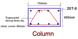
 Let us now calculate the cutting length of the trapezium-shaped stirrup as shown below.


Given data:

Column width = 750mm,

Column depth = 450mm.

Clear cover = 40mm.

Main bar dia. = 20mm.

The diameter of trapezium stirrup bar = d = 8mm. 

The cutting length formula for trapezium stirrup

= [(a + 2b + c ) +(2nos × hook length) - {(4nos. × bend > 90°) + (1no.× bend < 90° )}]

I have given a trapezium stirrup drawing showing h, a, b, & c., where blue colored line is the centerline of the trapezium stirrup.


First, we will calculate the value of c,a, & b.

c = [column width -{( 2nos.×clear cover) - (2nos. ×1/2 × dia. of stirrup)}]

   = [ 750mm - {( 2nos. × 40mm ) - ( 2nos. × 1/2 × 8mm )}]

   = [750mm - { 80mm - 8mm}]

  = [ 750mm - 88mm]

= 662mm.


a = [x + {(2nos.×1/2 × dia.of main bar) + (2nos. ×1/2 ×dia. of stirrup.)}]


Here, 

x = [column width -{(2nos.×cover )+( 2nos.× 1/2 dia. of stirrup)+ (2nos.× 1/2 dia. of main bar)}] ÷ 3

   = [ 600mm - {( 2nos. × 40mm ) + ( 2nos. × 1/2 × 8mm ) + ( 2nos.× 1/2 × 20mm )}] ÷ 3

   = [ 600mm - { 80mm + 8mm + 20mm }] ÷ 3

  = [ 600mm - 108mm ] ÷ 3

  = 492mm ÷ 3

 x162mm.

=  [x + {(2nos.×1/2 × dia.of main bar) + (2nos. ×1/2 ×dia. of stirrup.)}]

  = [ 162mm +{( 2nos.× 1/2 × 20mm ) + ( 2nos. × 1/2 × 8mm )}]

  = [ 162mm + { 20mm + 8mm }]

  =[ 162mm + 28mm]

a = 190mm.


I have drawn the triangle part of the trapezium stirrup, for your clear understanding. 


b =√( y )2 +( h )2

[ b is a hypotenuse of a triangle ]

Here,

 y =[ x+ (1/2 × dia. of stirrup)]

   = [162mm + (1/2 × 8mm.)]

y = 166mm.


h= [column depth - {(2nos ×clear cover) + (2nos.× 1/2 × dia. of stirrup)}]

  =[450mm - {( 2nos.× 40mm ) + ( 2nos. ×1/2 × 8mm )}]

  = [ 450mm - { 80mm + 8mm }]

  =  [ 450mm - 88mm ]

 h= 362mm.


b =√( y )2 +( h )2

   =√( 166 )2 +( 362 )2

  = √27556 +131044

=√158,600

= 398.246mm.


The cutting length of trapezium stirrup

= [(a + 2b + c ) +(2nos × hook length) - {(4nos. × bend > 90°) + (1no.× bend < 90° )}]

= [ { 190mm + (2 × 398.246mm) + 662mm } + ( 2nos.× 10d ) - {(4nos. × 3d) + (1no.× 2d )}]


{Here, 10d is taken as hook length, 3d for the bend > 90°, 2d for bend < 90° & d is stirrup bar dia.}

=  [ {190mm + 796.49mm + 662mm } + ( 2nos.× 10×8mm ) - {(4nos. × 3×8mm) + (1no.×2×8mm )}]

= [ 1648.49mm + 160mm - { 96mm + 16mm }]

= [ 1808.49mm - 112mm]

= 1696.49mm.


Share:

Calculating the cutting length of diamond stirrups in column by regular method./ Cutting length of diamond lateral tie in column.

If you are looking for a readymade calculator for diamond stirrups, then click here.

 For the calculation procedure, go through the following steps.👇


Diamond stirrup cutting length as per IS 2502.  Back 👈 Part 1

Let us now calculate the cutting length of a diamond stirrup as shown below.


Given data:

Column width = 600mm,

Column depth = 500mm.

Clear cover = 40mm.

The diameter of stirrup bar = d = 8mm. 


The cutting length formula for diamond stirrup

= [(4H) +(2nos × hook length) - {(2nos. × 135° bend) + (3nos.× 90° bend )}]

I have given a diamond stirrup drawing showing H, a & b


Here,
 H =√( a/2 )2 +( b/2 )2

( H is the hypotenuse of a triangle.)

First, we will calculate the value of a & b 

a = [ column depth - (2nos.× clear cover) - ( 1/2 × 2nos. × dia. of the stirrup bar).]

   = [ 500mm - (2nos.× 40mm) - ( 1/2 × 2nos. × 8mm) ]

    = [ 500mm - 80mm - 8mm ]

    = 412mm.


b =  [ column width - (2nos.× clear cover) - (1/2 × 2nos. × dia. of the stirrup bar).]

   = [ 600mm - (2nos.× 40mm) - (1/2 × 2nos. × 8mm) ]

    = [ 600mm - 80mm - 8mm ]

    = 512mm.

Now, 

        H =√( a/2 )2 +( b/2 )2 

           =√( 412/2 )2 +( 512/2 )2

=√( 206 )2 +( 256 )2

=√ 42436 + 65536

=√107972

= 328.59 mm.


The cutting length of diamond stirrup by the regular method

= [(4H) +(2nos × hook length) - {(2nos. × 135° bend) + (3nos.× 90° bend )}]

   Note:

1. Here,10d is taken for hook length.

2. We have deducted 2d for 90° bend -3nos., & 3d for 135° bend -2nos. ]


= [(4 × 328.59) + ( 2nos. ×10d ) - {( 2nos × 3d ) + ( 3nos × 2d )}]

= [ 1314.36mm + ( 2nos × 10 × 8mm ) - {(2nos × 3 ×8mm ) + (3nos × 2 × 8mm )}]

= 1314.36mm + 160mm - { 48mm + 48mm}]

= 1474.36mm - 96mm

=1378.36mm.= 1.378m

The cutting length of the diamond stirrup is calculated as per IS- 2502 for the same given data so that you can compare the difference between the cutting length in these two ways of calculation.

1. Cutting length of the diamond stirrup by the regular method = 1.378m

2. Cutting length of the diamond stirrup as per IS-2502 = 1.484m


The difference in cutting length = 0.106m

i.e. 7.69% more as per IS-2502.


  For BBS & cutting length of all types of structural members, click here.  


Share:

What is the difference between joggled bar & a staggered bar in civil construction?

1.  Joggled bar:

When we provide lapping in the reinforcement bars, we bend either of the two bars to align them with each other. These bent-up bars are called joggled bars in the civil field.


Sometimes, the bars provided in the structural members offset their original position due to technical and human errors. In such cases also, the bars are joggled, to bring them back to their required position from eccentricity.


Why do we joggle the reinforcement bars in the Civil construction?

1. To maintain the uniform clear cover for the reinforcement bars.


2. To bring back the drifted rebars in their specified position.

3. To maintain the center-to-center distance between the rebars.

4. To prevent the imbalance in the load transfer from one RCC structure to another.


2.  Staggered bar:

When we provide lapping in the bars, the level of the lapped part of the bar is kept in an up and down position from one another. This method of lapping in different levels in all types of structural members is called staggering of the bars.


Why do we provide staggered reinforcement bars in the lapping zone?


1. To prevent the buckling of the RCC structure.

2. To resist the lateral loads with a given factor of safety.
 
3.  To prevent the failure of the structure at the lapping zone.

4. To resist the bending moment and to safely transfer the superimposed load.

For you 👇

Why top bar should be joggled during lapping in columns?


Thank you for going through this article. Have a good day😄.

Share:

How to calculate the cutting length of 6 - legged stirrups?/ Calculating the cutting length of 6-legged lateral ties.

 Let us calculate the cutting length of 6-legged stirrups as shown below.


Given data :

Column width = 750mm.

Column depth = 600mm.

Corner bar 20T - 4nos.

Mid bar 16T - 8nos.

No. of stirrups - 3nos.

Dia. of all 3 stirrups = d = 8mm.

Clear cover = 40mm.


For your understanding, I have given different colors for all these 3 types of stirrups. 


1.   Stirrup -1:


Cutting length formula for stirrup-1

= [(2nos × a1) + (2nos. × b1) + (2nos. × hook length) - {(3nos. × 90° bend )+ (2nos. × 135° bend)}]

First, we will calculate the value of  a1 & b1

a1 = [(column width ) - {(2nos. × clear cover) + (2nos.× 1/2 dia. of stirrup-1 bar)}]

     = [ ( 750mm ) - { ( 2nos. × 40mm ) + ( 2nos. × 1/2 × 8mm )}]

     = [ 750mm - { 80mm + 8mm }]

     = [ 750mm - 88mm ]

     = 662mm.


b1 = [ x + ( 2nos.× 1/2 dia. of  mid bar.) + ( 2nos. × 1/2 dia of stirrup-1 bar )]

First, we will find out the value of x

x = [column depth -{(2nos.×cover )+( 2nos.× dia. of stirrup-3)+ (2nos.× 1/2 dia. of outer bar)}] ÷ 3

   = [ 600mm - {( 2nos. × 40mm ) + ( 2nos. × 8mm ) + ( 2nos.× 1/2 × 20mm )}] ÷ 3

   = [ 600mm - { 80mm + 16mm + 20mm }] ÷ 3

  = [ 600mm - 116mm ] ÷ 3

  = 484mm ÷ 3

 x = 161.33mm.


b1 = [ x + ( 2nos.× 1/2 dia. of  mid bar.) + ( 2nos. × 1/2 dia of stirrup-1 bar )]

    = [ 161.33mm + ( 2nos. × 1/2 × 16mm ) + ( 2nos. × 1/2 × 8mm )]

   = [ 161.33mm + 16mm + 8mm]

  = 185.33mm.


The cutting length for stirrup-1

= [(2nos × a1) + (2nos. × b1) + (2nos. × hook length) - {(3nos. × 90° bend )+ (2nos. × 135° bend)}]

= [ (2nos.× 662mm) + ( 2nos. × 185.33mm ) + (2nos. × 10d ) - {( 3nos.×  2d ) + ( 2nos. × 3d )}]


Note:

1. Here,10d is taken for hook length.

2. We have deducted 2d for 90° bend -3nos., & 3d for 135° bend -2nos. as similar to the above drawing in all the 3 types of stirrups.

  =[ 1324mm + 370.66mm + ( 2nos. × 10 × 8mm ) - {( 3nos.×  2× 8mm) + ( 2nos. × 3 × 8mm)}]

  = [1694.66mm + 160mm - { 48mm + 48mm }]

 = [1854.66mm - 96mm ]

= 1758.66mm.


2.    Stirrup-2:


Cutting length formula for stirrup-2

= [(2nos × b2) + (2nos. × a2) + (2nos. × hook length) - { (3nos. × 90° bend )+ (2nos. × 135° bend)}]

First, we will calculate the value of  b2 & a2

b2 = [(column depth ) - {(2nos. × clear cover) + (2nos.× 1/2 dia. of stirrup-2)}]

     = [ ( 600mm ) - { ( 2nos. × 40mm ) + ( 2nos. × 1/2 × 8mm )}]

     = [ 600mm - { 80mm + 8mm }]

     = [ 600mm - 88mm ]

     = 512mm.


a2 = [ y + ( 2nos.× 1/2 dia. of  mid bar.) + ( 2nos. × 1/2 dia of stirrup-2 )]

First, we will find out the value of y

y = [column width -{(2nos.×cover )+( 2nos.× dia. of stirrup-3)+ (2nos.× 1/2 dia. of outer bar)}] ÷ 3

   = [ 750mm - {( 2nos. × 40mm ) + ( 2nos. × 8mm ) + ( 2nos.× 1/2 × 20mm )}] ÷ 3

   = [ 750mm - { 80mm + 16mm + 20mm }] ÷ 3

  = [ 750mm - 116mm ] ÷ 3

  = 634mm ÷ 3

 y = 211.33mm.


a2 = [ y + ( 2nos.× 1/2 dia. of  mid bar.) + ( 2nos. × 1/2 dia of stirrup-2 )]

    = [ 211.33mm + ( 2nos. × 1/2 × 16mm ) + ( 2nos. × 1/2 × 8mm )]

   = [ 211.33mm + 16mm + 8mm]

  = 235.33mm.


The cutting length for stirrup-2

= [(2nos × a2) + (2nos. × b2) + (2nos. × hook length) - {(3nos. × 90° bend )+ (2nos. × 135° bend)}]

= [ (2nos.× 235.33mm) + ( 2nos. × 512mm ) + (2nos. × 10d ) - {( 3nos.×  2d ) + ( 2nos. × 3d )}]

=[ 470.66mm + 1024mm + ( 2nos. × 10 × 8mm ) - {( 3nos.×  2× 8mm) + ( 2nos. × 3 × 8mm)}]

= [1494.66mm + 160mm - { 48mm + 48mm }]

= [1654.66mm - 96mm ]

= 1558.66mm.


3.     Stirrup-3


Cutting length formula for stirrup-3

= [(2nos.× a3) + (2nos. × b3) + (2nos. × hook length) - {(3nos. × 90° bend )+ (2nos. × 135° bend)}]

First, we will calculate the value of  a3 & b3

a3 = [(column width ) - {(2nos. × clear cover) + (2nos.× 1/2 dia. of stirrup-3)}]

     = [ ( 750mm ) - { ( 2nos. × 40mm ) + ( 2nos. × 1/2 × 8mm )}]

     = [ 750mm - { 80mm + 8mm }]

     = [ 750mm - 88mm ]

     = 662mm.


b3 = [(column depth ) - {(2nos. × clear cover) + (2nos.× 1/2 dia. of stirrup-3)}]

     = [ ( 600mm ) - { ( 2nos. × 40mm ) + ( 2nos. × 1/2 × 8mm )}]

     = [ 600mm - { 80mm + 8mm }]

     = [ 600mm - 88mm ]

     = 512mm.


The Cutting length of stirrup-3

= [(2nos.× a3) + (2nos. × b3) + (2nos. × hook length) - {(3nos. × 90° bend )+ (2nos. × 135° bend)}]

= [ (2nos.× 662mm) + ( 2nos. × 512mm ) + (2nos. × 10d ) - {( 3nos.× 2d ) + ( 2nos. × 3d )}]

=[ 1324mm + 1024mm + ( 2nos. × 10 × 8mm ) - {( 3nos.×  2× 8mm) + ( 2nos. × 3 × 8mm)}]

= [2348mm + 160mm - { 48mm + 48mm }]

= [2508mm - 96mm ]

= 2412mm.


For you 👇

How to calculate the cutting length of 4-legged stirrups?

How to calculate the cutting length of a circular stirrup?

Share:

How to calculate the cutting length of triangular stirrups? / Cutting length of samosa ring.

 If you are looking for a readymade calculator for triangular stirrups, then click here.

 For the calculation procedure, go through the following steps.👇


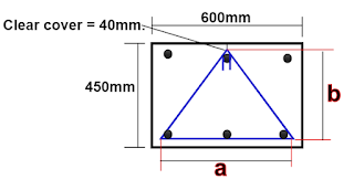
Let us now calculate the cutting length of triangular stirrups as shown below.


Given data:

Column width = 600mm.

Column depth = 450mm.

Clear cover = 40mm.

Stirrup dia. = d = 8mm.

The cutting length of the triangular stirrup is calculated by the formula

=[ (2 × H ) + a + (2nos.× hook length) - ( 4nos. × above 90° bend.)]


First, we will calculate the value of a & b as shown in the above drawing.

Here,

 a =[( column width ) - (2nos × clear cover) - (2nos. × 1/2 dia. of the stirrup)].

For a clear understanding, I have redrawn the triangular stirrup separately as shown below.


a = [ (600mm ) - ( 2nos. × 40mm ) - ( 2nos. × 1/2 × 8mm )]


   = [ 600mm - 80mm - 8mm ]

   = 512mm.


b = [( column depth ) - (2nos × clear cover) - (2nos. × 1/2 dia. of the stirrup)].

    = [ ( 450mm ) - ( 2nos. × 40mm ) - ( 2nos. × 1/2 × 8mm )]

    = [ 450mm - 80mm - 8mm]

    = 362mm.

The cutting length of the triangular stirrup

= [ (2 × H ) + a + (2nos.× hook length) - ( 4nos. × above 90° bend.)]


=√( a/2 )2 +( b )2

[ H is a hypotenuse of a (half ) triangle ]

=√( 512/2 )2 +( 362 )2

=√65536 +131044

√ 196580

=443.373 mm.


The triangular stirrup cutting length

= [ ( 2 × 443.373 ) + 512mm + ( 2nos. × 10d ) - ( 4nos.× 3d )]

{Here, 10d is taken as hook length , 3d for the bend above 90°, & d is stirrup bar dia.}

= [ 886.746 + 512mm + ( 2nos.× 10 × 8mm ) - ( 4nos.× 3× 8mm )

= [1398.746 mm + 160mm - 96mm.]

= 1462.746mm = 1.462m.


Note: Bend above 90° 👉 (2nos. of the hook bend + 2nos.) on the other two stirrup corners.

  For BBS & cutting length of all types of structural members, click here.  


 If you have any quarries, you can ask me in the comment box👇.

Thank you for going through this article. Have a good day😄.


Share:

Calculating the cutting length of circular slab bars. /How to calculate the cutting length of reinforcement bars in a circular RCC slab?

 Now, let us go through the procedure to find out the cutting length of the bars in a circular slab as shown below.


Given data :

Diameter of the circular slab = 1600mm = 1.6m.

Clear cover for the reinforcement = 25mm.

Rebar diameter = 10mm.    

Rebar spacing = 150mm c/c.


The formula for finding the length of the bar

=2√r2 - d2

Where, 

r = [diameter of the slab - (2nos.× clear cover )] ÷ 2

d = c/c distance of the individual bars from the central bar of the circle.


As you can observe in the above-given drawing, I have drawn a red-colored circle by deducting the clear cover. Radius r in the above formula will be the radius of this red circle. 

i.e. r = [1600mm - ( 2nos.× 25mm)] ÷ 2

         = [1550mm ] ÷ 2
    
        = 775mm.

The value of r will be the same for the cutting length calculation of every individual bar of the slab.


Note: All the rebars of the circular slab act as a chord of the red circle. To gain a basic understanding of this theory, you have to go through the article,


The length of the individual bars in the upper half part of the circular slab will be different.
The cutting length of the bars in the lower half portion will be equal to the upper half part bars.
I have named the bars for the half portion of the Circular slab, and let us find out the cutting length of each of these bars.


1. Cutting length of bar cc1
= diameter of red circle = 1550mm.

2. Cutting length of bar DD1

=2√r2 - d2

Here, d = 150mm.

= 2 × √7752 - 1502

   = 2 × √ 600625 - 22500

= 2 × √ 578125

= 2 × 760.345

  = 1520.69mm = 1.521m.


3. Cutting length of the bar FF1

Here, d = 300mm.

=2√r2 - d2

= 2 × √7752 - 3002

 = 2 × √ 600625 - 90000

= 2 × √ 510625

= 2 × 714.58

= 1429.16mm = 1.429m.


4. Cutting length of the bar GG1

Here, d = 450mm.

=2√r2 - d2

= 2 × √7752 - 4502

 = 2 × √ 600625 - 202500

= 2 × √ 398125

= 2 × 630.971

 = 1261.94mm = 1.261m.


5.Cutting length of the bar HH1

Here, d = 600mm.

=2√r2 - d2

= 2 × √7752 - 6002

 = 2 × √ 600625 - 360000

= 2 × √ 240625

= 2 × 490.535

 = 981.07mm = 0.981m.


6. Cutting length of the bar JJ1

Here, d = 750mm.

=2√r2 - d2

= 2 × √7752 - 7502

 = 2 × √ 600625 - 562500

= 2 × √ 38125

= 2 × 195.256

 = 390.51mm = 0.39 m


The calculation should be done until the cumulative value of d is less than r. So, we have calculated the cutting length of 5 bars on the upper side of the central bar CC1.


No. of bars in a circular slab 


The no. of top bars in  the circular slab
 
=[( diameter of the slab) ÷ c/c bar spacing ] +1

= [ (  1600mm ) ÷  150mm] +1

= 11 nos. 

That means 5 bars on either side of the central bar CC1

Total no. of bars 

= Top bars + Bottom bars

= 11nos + 11nos.=22nos.

As the upper half part of the circle is identical to the bottom half part, you will have 2nos of central common bars and 4 nos of the chord bars having the same cutting length.

1. Cutting length of central bar CC1 = 1.55m 👉 2nos.

2. Cutting length of bar DD1           = 1.521m 👉 4nos.

3. Cutting length of bar FF1            = 1.429m 👉 4nos.

4. Cutting length of bar GG1           = 1.261m 👉 4nos.

5. Cutting length of bar HH1           = 0.981m 👉 4nos.

6. Cutting length of bar JJ1             = 0.390m 👉 4nos.

                                                                         --------------

                                                                             22nos.


Share:

Translate

Blog Archive

popular posts

Recent Posts

Google search